Table of Contents
— Othmane Oubejja 2017/11/30 17:33

FPGA-based IEEE 802.15.4 PHY Transmitter via Custom Bitstream (PicoSDR)
IEEE 802.15.4 is part of the IEEE 802.15 communication protocols for WPANs, which includes other famous standards such as IEEE 802.15.1 (Bluetooth), and IEEE 802.15.3 (UWB Wireless). IEEE 802.15.4 specifies the MAC and PHY Layers for Low-Rate WPANs (LR-WPAN), and is currently used for a large variety of network protocols, including ZigBee, 6lowPAN and TinyOS.
In this tutorial we will focus on the PHY layer exclusively and, in order to encode/decode packets, we will use a (very) light MAC frame structure using Intel HEX data format. (which has nothing to do with the native 802.15.4 MAC Frame Structure !)
What's new here ?
As seen in the previous tutorials, operations such as FFT, MUX/DEMUX, encoding, modulation,… are processed via GNU Radio blocks all over the flow graph. In other words, the transmitted waveform is “soft shaped” by GNU Radio.
The goal of this tutorial is to transmit IEEE 802.15.4 packets with a “Hard” transmitter, it means that the waveform is generated by the PicoSDR, by taking a .hex file as an input and processing it through an FPGA design, using IP cores written in hardware description language (HDL) code.
In this tutorial, we will see how to transmit and receive IEEE 802.15.4 packets using a .hex file as an input and a custom Bitstream of a IEEE 802.15.4 PHY Layer Transmitter targeting the Xilinx FPGA Virtex6 of the PicoSDR
Setup
Install gr-cortexlab
We will need some blocks of the module gr-cortexlab. Normally, if you followed the previous tutorials (highly suggested!), you might have started by installing The FIT/CorteXlab Toolchain, which automatically installs this module.
Find the Bitstream
In order to use the FPGA Transmitter design, we will have to load the custom Bitstream on the transmitter node(s). The Bitstream is loaded in the Airlock server of CorteXlab, and can be found in :
/cortexlab/fpga/picotx802154sx315.bit
Copy the file in your main directory :
you@srvairlock:~$ cp /cortexlab/bitstreams/pico_tx802154_sx315.bit .
The receiver node(s) will run the default Bitstream (Pass-through design)
FPGA transmitter Design
We will follow the IEEE 802.15.4 Option 3 global specification, which operates in the 2450 MHz band with an O-QPSK digital modulation.
Block diagram :

GRC Flow graphs and Python files
Transmitter
Generate .hex file as an input source
Here is a simple tool for creating/editing HEX data : Bless Hex Editor.
An example to create a packet containing : Successful reception of FPGA generated frame :

TX Flowgraph in GRC (ieee802154_tx_pico.grc)
The PicoSDR needs some initializing stuff to be done :
- Add and configure these blocks as seen in previous PicoSDR tutorials :
- RTDEx Sink
- ATTENTION : Channel parameter has to be set to 3 as in the previous image. That's the only channel that allows access to the custom design.
- Custom Register (CR 1 & 4)
- Set CR1 value to 0 to enable the transmitter
- Set CR4 value to 0 to disable MIMO synchronization
- Radio420
- The Radio420x is a Multimode SDR FMC RF transceiver. PicoSDR 2×2 contains 2 Radio420M modules which are MIMO capable (M for MIMO, pretty smart, huh ?). It is mandatory to initialize BOTH radio cards, even if only 1 is used. So, since our device contains 2 Radio420M transceivers, it means we will have 2
Radio420 TXblocks and 2Radio420 RXblocks. Here is a product sheet for more info. - To be short, add 2
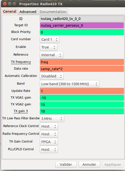
Radio420 TXblocks and 2Radio420 RXblocks - Now, we only need one transmitter per node, so make sure to enable only the Radio420 TX of Card 1, and set the gain values as following :
- For the 3 remaining
Radio420blocks, we only need to disable them by setting the Enable parameter to False

If you don't get this part, have a look here.
There isn't that much left in here since all baseband processing is done by the FPGA. All you have to do now is to connect a File Source block to the RTDEx Sink block, and specify the absolute path to your “.hex” file in File Source block parameters :

The final flow-graph of your transmitter should look like this :

Receiver (ieee802154_rx_pico.grc)
not finished

Generate .py files
Under GRC, press this button: 
Create Scenario (.yaml file)
We will use for example the node12 as the transmitter and the node31 as the receiver.
- The TX node will have the Custom Bitsream, so we kindly ask Minus CLI to load it in the Node12 :
nodes:
  node12:
    command: ./ieee802154_tx_pico.py
    bitstreamA: pico_tx802154_sx315.bit
- The RX node will have the default Bitstream that makes received/emitted data goes through the RTDEx FPGA core without any DSP operation :
node31:
    command: ./ieee802154_rx_pico.py
The complete scenario should look like this :
# Scenario textual description
description: 802.15.4 PHY FPGA Transmitter

# Experiment maximum duration
#   Time after which the experiment is forced to stop in seconds
duration: 50

nodes:
  node12:
    command: ./ieee802154_tx_pico.py
    bitstreamA: pico_tx802154_sx315.bit

  node31:
    command: ./ieee802154_rx_pico.py
Upload files and run the experiment
The experiment directory should look like this by now :
...
├── pico_zigbee
│   ├── frame_fpga.hex
│   ├── ieee802154_rx_pico.py
│   ├── ieee802154_rx_pico.grc
│   ├── ieee802154_tx_pico.py
│   ├── ieee802154_tx_pico.grc
│   ├── scenario.yaml
│   ├── pico_tx802154_sx315.bit
...
The .grc files are not needed to create the task, but if ever you want to change/debug your flow graph it's more practical to do it in GRC rather than reading the generated .py file.
Now you have to upload the files to Airlock server and book the testbed.
Create the task :
you@srvairlock:~$ minus task create path/to/the/folder/pico_zigbee
And submit it :
you@srvairlock:~$ minus task submit pico_zigbee.task
Check results
Check the experiment status :
you@srvairlock:~$ minus testbed status
And when the task is finished you should get this message :
you@srvairlock:~$ minus testbed status
num total tasks:   xxxx
num tasks waiting: 0
num tasks running: 0
tasks currently running:
  (none)
Then proceed to extract results of the RX node(s). In our case it's the Node31 only.
The file tree should look like this :
...
├── pico_zigbee.task
├── pico_zigbee
├── results
│   ├── task_xxxx
│   │   │   ├── node31
│   │   │   │   ├── ieee802154_rx_pico.grc
│   │   │   │   ├── ieee802154_rx_pico.py
│   │   │   │   ├── ieee802154_tx_pico.grc
│   │   │   │   ├── ieee802154_tx_pico.py
│   │   │   │   ├── scenario.yaml
│   │   │   │   ├── scenario.yaml~
│   │   │   │   ├── pico_tx802154_sx315.bit
│   │   │   │   ├── impact_instr.txt
│   │   │   │   ├── frame_fpga.hex
│   │   │   │   ├── _impactbatch.log
│   │   │   │   ├── stderr.txt
│   │   │   │   ├── stdout.txt

...
Open the stdout.txt file to check if the transmission was successful.
Note : don't worry if stderr.txt is non empty, there is always some missing packets
nutaq_carrier_perseus_0 connected to 192.168.0.101
Registering carrier nutaq_carrier_perseus_0
Using Volk machine: avx_64_mmx_orc
Global init begin
radio420_tx::InitRadio420x: 1
    Powering up hardware
    Resetting hardware
    Configuring PLL
      - Reference frequency 30720000 Hz from internal oscillator
      - Acquisition frequency 16000000 Hz
      - Lime frequency 30720000 Hz
    PLL is locked
radio420_rx::InitRadio420x: 1
    Automatic calibration
rx ended
radio420_rx::InitRadio420x: 2
    Resetting hardware
    Configuring PLL
      - Reference frequency 30720000 Hz from external connector
      - Acquisition frequency 16000000 Hz
      - Lime frequency 30720000 Hz
Error: PLL is not locked
rx ended
radio420_tx::InitRadio420x: 2
rtdex_source: Init
rtdex_source: Device MAC Address: 00:d0:cc:0a:01:98
rtdex_source: Host MAC Address: 78:d0:04:20:74:b7
Global init end successfully
rtdex_source: End Good
**************************************************
53 :75 :63 :63 :65 :73 :73 :66 :75 :6C :20 :72 :65 :63 :65 :70 :74 :69 :6F :6E :20 :6F :66 :20 :46 :50 :47 :41 :20 :67 :65 :6E :65 :72 :61 :74 :65 :64 :20 :66 :72 :61 :6D :65 :
**************************************************
==================================================
Successful reception of FPGA generated frame
==================================================
**************************************************
53 :75 :63 :63 :65 :73 :73 :66 :75 :6C :20 :72 :65 :63 :65 :70 :74 :69 :6F :6E :20 :6F :66 :20 :46 :50 :47 :41 :20 :67 :65 :6E :65 :72 :61 :74 :65 :64 :20 :66 :72 :61 :6D :65 :